Half wave voltage modulation of LiNbO 3 modulator
Half-wave voltage is one of the essential parameters of the LiNbO3 electro-optic modulator. It refers to the voltage required for phase change π, usually expressed in V π. However, it isn't easy to detect the phase of light in optics because it is not easy to measure the stage directly. Therefore, the detection of phase is usually transformed into the detection of light intensity, frequency, and other physical parameters that are easy to be measured directly. Several commonly used half-wave voltage measurement methods are optical communication simulation method, frequency doubling modulation method, and extreme value measurement method.
The simulation method of optical communication converts the modulated signal into the sound signal. It connects the player at the external modulation input when the modulated sine signal is cut off. The output signal is played through the power output port's loudspeaker, and the demodulation amplitude controls the volume. In the DC voltage process increasing gradually, the sound will have two times minimum volume and distortion. The difference between the two times of voltage is Half-wave voltage measured. The advantage of this method is that the measurement is simple. Still, because the minimum value judgment is too rough in the measurement process, the accuracy of the measurement data is not high.
The basic principle of frequency doubling modulation is to load DC voltage and AC signal simultaneously. When DC voltage is adjusted to the voltage value corresponding to the extreme value of output light intensity, the output AC signal will appear frequency doubling distortion. The difference of DC voltage corresponding to frequency doubling distortion is a half-wave electric voltage.
The extremum measurement method's basic principle is not to load the modulation signal on the phase modulator but only to load a DC voltage. When the magnitude of the DC voltage is gradually changed, the extremum can be determined by the designed interferometer optical path's output light intensity. The difference between the adjacent maximum and minimum DC voltage is the half-wave voltage. This method is relatively simple, but it requires high stability of the light source.
Next, we will introduce several accurate and effective half-wave voltage test methods of the LiNbO 3 modulator for your reference
1.Using sawtooth wave to measure half wave voltage
This method is suitable for the low-frequency half-wave voltage test of phase modulator and intensity modulator. The test principle is shown in Figure 1.
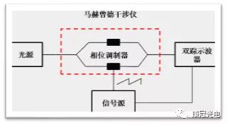
图1半波电压测试系统原理图
When the electric field v (T) is loaded on the Mach Zehnder interferometer's interference arm, the light input field will produce a phase shift φ (T) on the arm due to the electro-optic effect. For the light area with the input of EIN (T), the total output light field function is:
Eout=Ein(t)cos【φ(t)】=Ein(t)cos【πv(t)/vπ】 (1)
V π is the half-wave voltage of the phase modulator on the arm; the curve of output light field changing with voltage is shown in Figure 2. from can see, the voltage change corresponding to a half cycle of sine signal is the half-wave voltage.
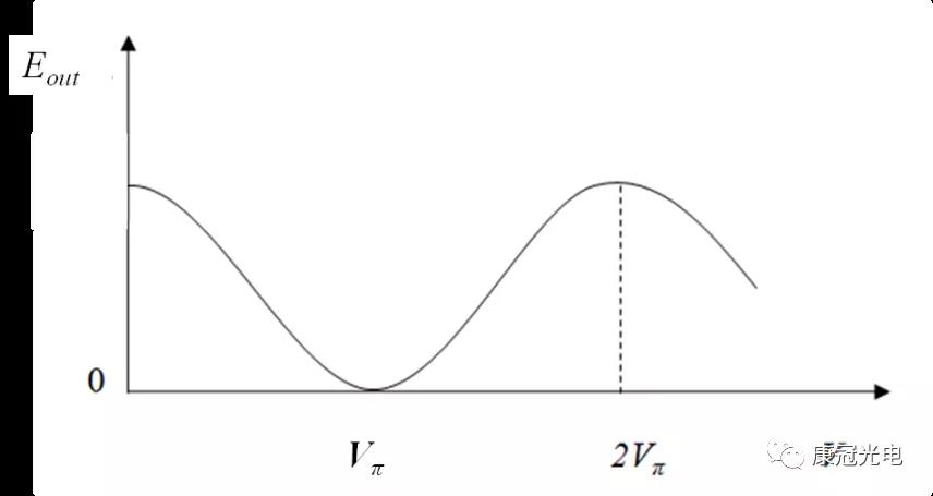
Fig. 2 output light field of Mach Zehnder interferometer changing with voltage
Different from the extremum method, the half-wave voltage measurement method of Mach Zehnder interferometer loads a sawtooth wave signal instead of a DC signal on the phase modulator, which can avoid the influence of random phase change caused by external factors (such as temperature change, vibration, etc.). The sawtooth signal and the output light signal are tracked simultaneously by an oscilloscope. For half-wave voltage can be calculated by comparing the periods of the two signals. This method avoids the error of extremum judgment in extremum measurement and improves the measurement accuracy.
Suppose that the loading period of the sawtooth wave signal on the phase modulator is T1, and the period of the output sine signal is T2. The motion shown in Figure 3 can be detected on the oscilloscope. According to the half-wave voltage formula (2) described in Section 3.2, it can be concluded that:
Vπ=VPP /2*(T1/T2) (2)
Where VPP refers to the peak value of sawtooth wave, viz. VP + - VP -.
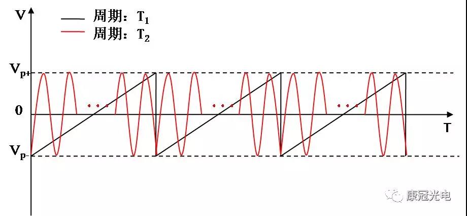
Figure 3 output signal of oscilloscope
2. Using square wave signal to measure half wave voltage
This test method is suitable for the half-wave voltage test of the intensity modulator. If the phase modulator is tested, the MZ interference system can be built for a test. The schematic diagram of the method is as follows:

Figure 4 Schematic diagram of half wave voltage test of square wave signal
Note: (1) the modulator should adjust the bias voltage to make it work in the linear region, and ensure that the detector works in the linear region;
(2) the output impedance of the signal source should match the impedance of the RF end of the modulator (50 ohms).
After connecting the system according to the figure above, the square wave signals VPP increases gradually. We can see on the oscilloscope that the amplitude of the square wave signal increases with the increase of VPP, reaches the maximum value, and increases VPP. The oscilloscope shows that the square wave is distorted until the situation, as shown in Figure 5 (c) occurs, and records the VPP value。


Figure 5 oscilloscope output waveform change
In this case, the RF half wave voltage can be calculated according to the following formula:
Vpi=Vpp/2 (3)
Note: if the signal source output is in high resistance state, the actual voltage loaded on the modulator is about 1 / 2 * VPP, and the half wave voltage should be multiplied by 1 / 2.
The above two methods are suitable for the measurement of the low-frequency lower half-wave voltage of the modulator. Please refer to the following two documents that will not be introduced in detail for the high-frequency lower half-wave voltage measurement method.
1、魏正军,等. 基于萨尼亚克光纤干涉仪的相位调制器半波电压的测量方法[J],光学学报,2011, 31(6).
2、贾喻鹏,等. 基于光谱分析的强度调制器半波电压测量[J] ,北京工业大学学报,2015,41(12).


