introduction:
The traditional instantaneous frequency measurement receiver adopts the electronic method, providing a 0.5 ~ 18GHz frequency test (the sensitivity is not higher than - 50dbm). The structure is complex, the volume is enormous, the cost is expensive, and it is vulnerable to electronic interference. A millimeter-wave band (0.5 ~ 4oghz) signal has been put into use in electronic warfare systems in recent years. It is difficult for traditional detection methods to achieve such a large bandwidth operation. Microwave photonic technology provides the possibility to improve the performance of instantaneous frequency measurement receivers. It can provide a solution with broadband frequency measurement, low loss, anti-interference, and a small portable system. Using microwave photonics to realize instantaneous frequency measurement of microwave signal can overcome the electronic bottleneck and adapt to the complex electromagnetic environment. It is expected to replace the traditional electronic methods and has a strong application prospect.
1. Instantaneous measurement of microwave frequency based on intensity modulation
Modulate the radio frequency signal to be measured to two lightwave signals with different wavelengths. After passing through a microwave photonic filter with a sinusoidal transfer function, use a wave divider to separate the modulated light carrier signals with two different wavelengths, as shown in Figure 1.
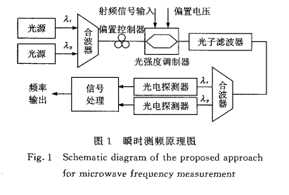
Optical signals of different wavelengths are converted into electrical signals by two photodetectors for subsequent circuit processing. The system has additional requirements for the center frequency of two light sources: the center frequency of one light source should be the band-pass frequency of the filter, and the center frequency of the other light source should be the suppression frequency of the filter. In this way, an amplitude comparison function with good linearity can be obtained, which helps reduce the test error. After signal processing, the amplitude comparison function can be obtained as follows:

Where: is the frequency of the RF signal to be measured, FSR is the free spectrum range of the filter, and a suitable value can be obtained by designing different filter parameters. It can be seen from the above formula that the amplitude comparison function is only related to the frequency of the signal to be measured, so it is not affected by the fluctuation of light source power and the power of the signal to be measured. The microwave frequency of 0 ~ 2 GHz is measured in the experiment, and the error is within ± 0.2 GHz. But in this structure, the Sagnac ring is used as the photonic filter, which affects the system's stability. The offset point drift of the optical modulator reduces the test accuracy, and the system is not reconfigurable, so the test range and resolution can not be adjusted. It has a complex structure, many optical devices, and high cost. A solution of tunable bandwidth and resolution for microwave frequency measurement is proposed by the microwave photonics laboratory staff, University of Toronto, Canada. The optical structure is shown in Fig. 2.
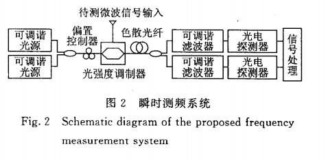
Two tunable light sources generate the carrier signal. The signal to be measured with unknown power and frequency is modulated to the optical carrier through a maser modulator. Different dispersion is introduced to the runners of two different wavelengths through a dispersion fiber, making the modulation carrier signal of different wavelengths generate extra power compensation. Through two tunable microwave photon filters, two different wavelengths of the signal are modulated. The carrier signal is separated, and the photoelectric detector obtains the microwave signal's power to be measured. After the subsequent processing, the amplitude comparison function only related to the microwave signal frequency can be obtained. By adjusting the wavelength interval of two carrier light sources, the system's frequency measurement bandwidth can be changed without changing the optical path structure. Two carrier light sources need to have a larger wavelength interval to obtain a higher frequency measurement resolution.
The optical circuit structure is used to realize instantaneous frequency measurement, and there is a balance between the frequency measurement bandwidth and the frequency measurement accuracy. The high-frequency measurement accuracy is usually at the cost of narrow frequency measurement bandwidth. Suppose multiple light sources are used to generate different wavelengths of carriers. In that case, the resolution of measurement can be improved while maintaining a large frequency measurement bandwidth, but the structure's complexity and cost will be increased. In the experiment, the accuracy of ± 0.02ghz is achieved in the frequency range of 11-13.6ghz. This method has a relatively high-frequency measurement accuracy and can accomplish the tuning of frequency measurement bandwidth and resolution by carrier light source. However, carrier light sources' requirements are strict, and the frequency measurement bandwidth is greatly affected by carrier light sources. Niushasarkkhosh and others used the laser semiconductor amplifier's nonlinear effect to mix two differential delay optical carriers and establish the relationship function between microwave frequency and the development of a laser semiconductor amplifier [3]. The microwave frequency measurement of 2-20ghz was successfully realized, and only a low-cost DC photodetector was used to reduce the system cost.
2. Instantaneous measurement of microwave frequency based on phase modulation:
The instantaneous measurement of microwave frequency using a maser intensity modulator requires a complex circuit to control the DC bias point of the maser intensity modulator, which is easy to introduce measurement error. Instead of the frequency measurement scheme of the easier intensity modulator, the modulator's DC bias point is not set, which avoids the system's instability caused by the bias point's drift. Also, the phase modulator is simple in structure and less insertion loss, and is more suitable for practical application. Reduce the system's cost, and a single light source can generate the carrier signal. The purpose of instantaneous frequency measurement can be achieved using phase modulation technology and two different optical paths. The optical path structure is shown in Figure 3.
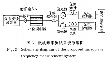
A distributed feedback laser generates the carrier signal, and the polarization-maintaining fiber is used to connect the optical components. The carrier signal passes through the half-wave plate, and the central axis of the half-wave plate is adjusted to form L45 with the slow axis of the polarization-maintaining fiber. Two orthogonal polarization continuous optical carriers are generated, respectively, transmitted to the phase modulator along the slow axis and fast axis of the polarization-maintaining fiber—the microwave signal to be measured drives the phase modulator to generate the modulated carrier signal. The password is divided into two parts of equal power and equal polarization through the polarization-maintaining coupler, as shown in Fig. 3: the upper arm signal passes through a section of polarization maintaining fiber, and the polarization angle of the polarizer is adjusted to make it consistent with the phase modulator The slow axis of PMF is 135... Due to the power degradation caused by differential group delay, the modulated carrier signal experiences a low-pass filtering effect. The low-pass filtering effect can be expressed as:

The plant's frequency is the microwave signal to be measured and the differential group delay value introduced by polarization-maintaining fiber. A section of dispersion compensation fiber is introduced into the lower arm, and the polarizer on the peninsula is adjusted to make its polarization axis consistent with the slow axis of the polarization-maintaining fiber so that the optical signal is transmitted only along the slow axis enters the dispersion compensation fiber through the polarizer. The power degradation caused by dispersion compensation fiber makes the modulated carrier signal undergo a band-pass filtering effect. The transfer function of the band-pass filtering effect can be expressed as follows


The low-pass and band-pass filtering effect of the modulated carrier signal is realized, which replaces the expensive microwave photonic filter and reduces the cost. Because the low-pass and band-pass filtering effects have notch frequencies and zero frequencies, the amplitude comparison function with good linearity can be obtained. The measurement range of microwave frequency can be changed by changing the length of dispersion fiber and polarization-maintaining fiber. In the experiment, the microwave bandwidth of 1.7 ~ 12.2ghz is measured with high precision, and the measurement error is less than ± 0.07ghz, which can meet the practical needs.
本文摘自《微波光子技术在瞬时测频中的应用》


